Optimized injection molding tool facilitates direction-dependent characteristic value determination and reliable component design.
AUTOMATED PROCESS MONITORING AND MATERIAL DOCUMENTATION
An injection molding tool optimized at Fraunhofer LBF facilitates the production of short glass fiber reinforced unidirectional plates for the production of highly oriented specimens under different removal angles. The tool was designed to ensure that the reinforcing fibers are oriented approximately unidirectionally (UD) in the direction of flow. Test specimens for the tensile tests can be removed from the plate at any angle to the flow direction to determine parameters for the material description. This facilitates resource-conserving component design that is suitable for the materials.
The new plate enables the production of UD specimens for tensile tests. Based on the test results, material models can be adjusted. This facilitates component design that is suitable for the materials. By exploiting the mechanical properties of the material, components of minimal weight can be designed reliably, which protects the environment and resources.
Superposition of fiber and matrix
By reinforcing a thermoplastic material with fibers, the physical properties are modified: Tensile strength and rigidity are increased and thermal expansion reduced [1]. Material behavior consists of the properties of the fibers and the polymer matrix. The objective of this combination is to develop a new material that is superior to the properties of the individual components. Regardless of fiber content, fiber-reinforced plastics reach many times the strength values in the transverse direction under load parallel to the fiber direction.
The analytical description of the superposition of fiber and matrix via micromechanical approaches is the topic of the research. Detailed knowledge of macroscopic, directional material data is urgently needed. According to the current state of knowledge, there is no all-encompassing model that accounts for anisotropy.
Tensile tests below 0° and 90° compared to the flow direction are essential for the acquisition of the material data. Experiments under additional angles are advantageous for reliable modeling.
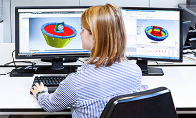
Integrative Simulation
The fibers contained in the plastic melt align in the cavity of the tool during injection molding. When the cavity is filled, the flow-induced distribution of the reinforcing fibers and shear forces close to the mold wall give rise to locally anisotropic material properties. The manufacturing process must therefore be included in the analysis of the mechanical properties during component design. The integrative simulation, which links the simulation of the injection molding process with the subsequent FEM calculation, has become a powerful tool in component design.
In general, two boundary layers and a core layer form over the component thickness. The fibers in the boundary layers are oriented in the flow direction of the melt, while the fibers in the core layer are orientated orthogonally. In the direction of thickness there are negligibly few fibers. The orientation tensor specifies the local fiber orientation.
Micromechanical approaches and available test specimens
With micromechanical models, the anisotropy of stiffness and strength as well as non-linear and yield strength-dependent properties of the matrix and a material failure due to matrix failure, fiber failure and fiber matrix debonding can be mapped locally [2].
Uniaxial material data are required for micromechanical modeling and phenomenological criteria. For a description of the failure behavior that is suitable for the materials, it is necessary to test samples with unidirectional fiber orientation. Hence, different test specimens are used. Frequently, test specimens are taken from plates of three-layer structures at different angles to the filling direction. It is customary to pour the dumbbell test specimen (Fig. 1) of type 1A from DIN EN ISO 527-2, also known as Campus rod, directly into the injection mold. It features high orientation and a three-layer structure, but is too narrow to allow taking samples across the injection direction. With a thickness of 4 mm, it is not a representative injection-molded part. Material-specific characteristic values for modeling cannot be clearly determined this way. The evaluation of the failure behavior of the material is problematic.

An existing test specimen with a high fiber orientation in the test area is illustrated in Fig. 2. With a thickness of 2 mm it represents a typical injection molded part. A disadvantage of this test specimen geometry is that, with a width of 20 mm, the test area does not permit the removal of samples below 90°.
Concept of UD plate
The current state of research shows that there is a need for a UD plate that allows extraction of test specimens orthogonal to the filling direction. The findings from experiments at different angles on UD plates will help to fit, compare and expand different micromechanical models and phenomenological criteria.
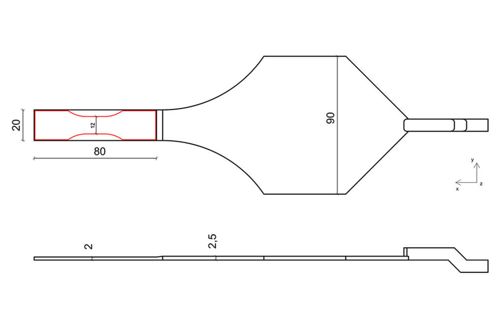
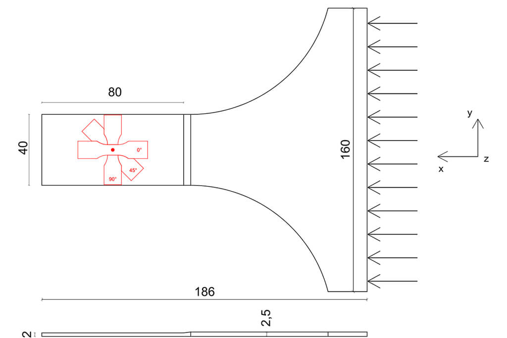
The UD plate (Fig. 3) is designed to be manufactured on a standard injection molding machine. Thus, it is inexpensive and accessible to SMEs. Test specimens 1BB or 5B according to DIN EN ISO 527-2 can be removed at any angle to the flow direction. This makes the plate a simple tool for determining measurement data for further enhancement of existing material models.
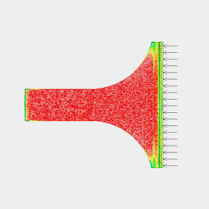
The injection molded part is filled through a film gate. This way, the melt can be introduced with a planar flow front. The reduction in thickness accelerates the melt, in the same way as the cross-section taper, which gives the fibers an initial orientation impulse. With pre-oriented fibers, the melt flows in the testing area and and forms the final UD orientation due to flow-induced shear forces.
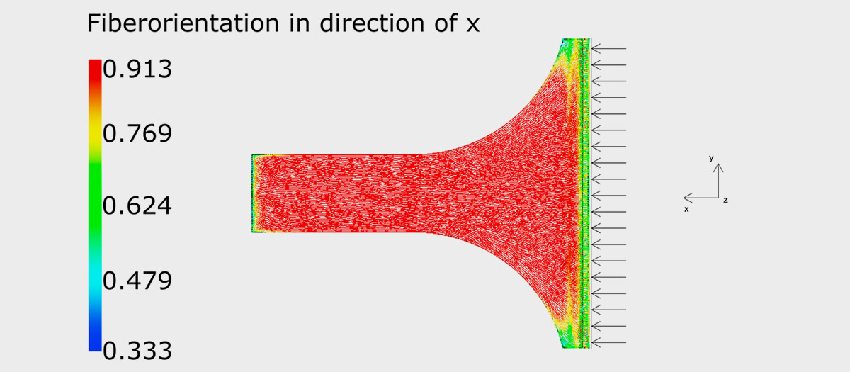
Experiment: Determination of fiber orientation
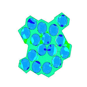
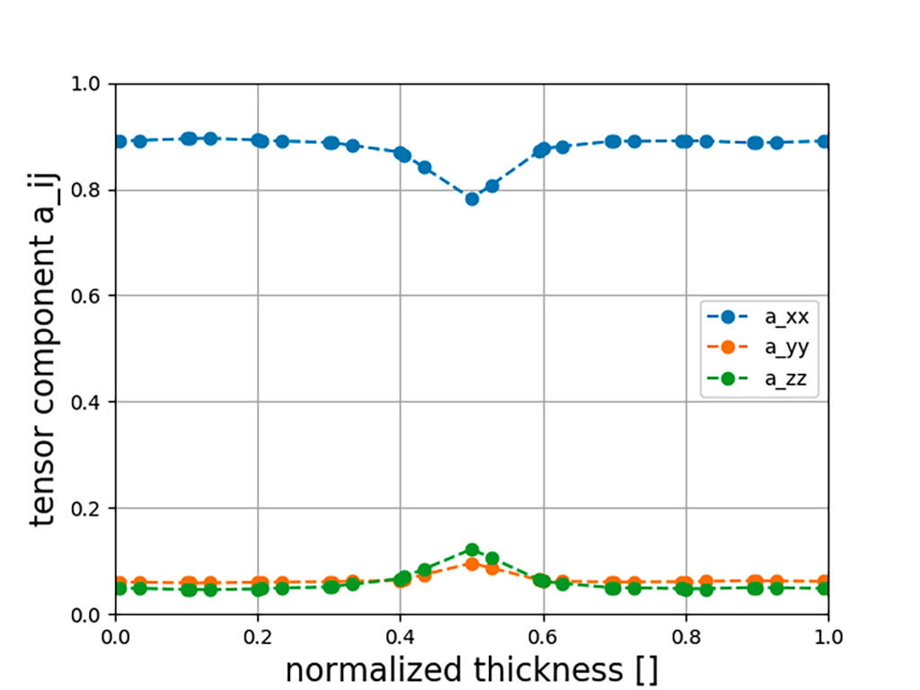
Figure 4 shows the fiber orientations at the center of the test area (see Fig. 3, red dot in the center of the test specimen) of the UD plate. Filling takes place in the x-direction; y describes the width direction and z describes the thickness direction. A substantial middle layer is present when the majority of the fibers (> 50%) lie in the y-direction. This is clearly not the case here. The simulation results demonstrate that the fiber orientation in the filling direction is between 0.89 and 0.78. In the y- and z-directions there are a maximum of 11% fibers.
Customer benefits
The new test specimen geometry will provide angle-specific material characteristics. Thus, the material modeling can be optimally adapted and the customer gains precision and competitive advantages when designing a new component.
References
[1] Schoßig, M., Grellmann, W. & Mecklenburg, T.: Characterization of the fracture behavior of glass fiber reinforced thermoplastics based on PP, PE-HD, and PB-1. Journal of Applied Polymer Science 115 (2010) 4, pp. 2093 – 2102
[2] Nutini, M. & Vitali, M.: Interactive failure criteria for glass fibre reinforced polypropylene: validation on an industrial part. International Journal of Crashworthiness 37 (2017) 1971, pp. 1 – 15
[3] Amberg, J.: Ermittlung temperaturabhängiger anisotroper Stoffwerte für die Spritzgießsimulation. [Determination of temperature-dependent anisotropic material values for injection molding simulation.] AiF Research Report 13220 N, Deutsches Kunststoff-Institut DKI, Darmstadt (2004)

“The determination of angle-dependent characteristic values is also important with regard to environmental protection. After all, components that are already reliably designed at an early stage can be developed with minimal weight and materials, which saves resources!” Tamara van Roo, M. Eng.
Contact
- Tamara van Roo, M. Eng.
- Phone: +49 6151 705-8994
- tamara.van.roo@lbf.fraunhofer.de